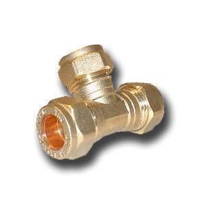
I think your thinking of this valve design as a typical piston type, where you have 3 ports: one barrel, one tank or pressure system with pilot valve, and one exhaust reservoir, similar to a QEV or sprinkler valve.
Its actually very closely related to technicians QDV as explained here.
http://www.spudfiles.com/forums/t-t17858.html
It differs in that: his is housed inside a tank, and mine is housed inside a Tee fitting.
The bolt wouldn't move as you begin adding pressure, the o-rings would catch and seal on the tubing that it sits in.
there is no "equalization of pressure" because the bolt/piston is operated manually (eliminating the need for a pilot valve because there is no pressure behind the bolt/piston)
concerning the o-rings, perhaps my drawing is inaccurate but the design does indeed call for floating o-rings in all 4 locations (creating a tight seal keeping air ONLY in the center of the Tee as depicted in the drawing... until you intentionally pull back the bolt that is.).
You are quite correct in your comment concerning operating this valve by hand... it would hurt... the all-thread is tapped into the bolt/piston and the whole assembly moves as a unit. However, it wasn't designed to be operated by hand. The steel lock-nuts on the end of the all-thread act as a ledge that a standard trigger assembly can press against, basically operating it remotely. Quite similar to the way this airgun engages the slide valve.
http://i39.servimg.com/u/f39/14/59/04/00/photo010.jpg
Please read and understand before posting. The picture clearly illustrates and says that its operated via trigger, among other things. Instead of just saying "WRONG" some thoughts as to how to fix the possible issues would have been nice. I dont mean to come off as a jerk, but I worry that others will be less likely to study my diagram once it has been discounted, and I truly want feed back (even if it does turn out to be a flop).
sorry for the wall of text


 olive -->
