Possible rifling made easy?
-
rna_duelers

- Staff Sergeant 3

- Posts: 1739
- Joined: Mon Sep 26, 2005 7:07 am
- Location: G-land Australia
well myn worked fine,and its simpler and easyer then any cables,gears and things,plus i have proof of it working(but there is some doubt) i'll choose to use what works and what is *easy*.but if you did build a rig to do that it would turn out nicely the rifleing would be perfect without any flaws like my method,because my barrel has a crappy bit of rifling about 2 inches at start but fromt hen on i got the twists right and consistent.Keep your mind going because i would like 2 see a machine made.

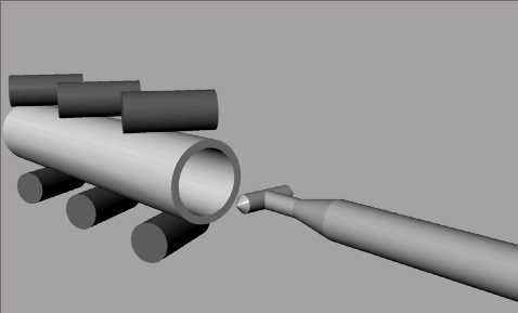
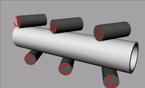
Here is my idea I have... The cutter remains stationary while the pipe rotates . Vice versa could be done. Basically only the front two rollers would need to be powered while the others just strudy. The rollers would need to be coated with something like rubber so that they can "grip". Very similar to the nail gun someone introduced (Cant remeber if it was B the B or Rambo). By simply adjusting the angle of these rollers you could adjust the twist rate.
<img src="http://www.spudfiles.com/uploader/uploadFiles/R-01.PNG">
<img src="http://www.spudfiles.com/uploader/uploadFiles/R-02.PNG">
<img src="http://www.spudfiles.com/uploader/uploadFiles/R-03.PNG">
Tell me what you think and if you have any improvments. After making these drawings I found many things that can be made simpler.
-
zvallance1
- Private 4

- Posts: 94
- Joined: Wed Dec 21, 2005 11:34 pm
so rna, have you actaully made something that rifles barrels? because thats what it seems like you're saying...if so, GET A PICTURE UP HERFOR US!rna_duelers wrote:well myn worked fine,and its simpler and easyer then any cables,gears and things,plus i have proof of it working(but there is some doubt)
and pimpmann, nice idea...kind of like what i initially suggested, but with a nice twist on it =)
It looks like you're pretty good with Rhino 3D, too...any chance you could incorperate, and then model all the ideas that we've come up with in this thread?
I gave it a go last night, but I couldn't get the program to do anyhting the way i wanted it to...
Great ideas guys, keep 'em coming!
I actually like creating 3D renderings, so yes if someone wants me I can help them by creating a model. I would rather teach them how to do so though... First ill have to understand what in the f*ck is going on with your designs.
-
jrrdw

- Moderator


- Posts: 6572
- Joined: Wed Nov 16, 2005 5:11 pm
- Location: Maryland
- Has thanked: 39 times
- Been thanked: 22 times
- Contact:
Pimpmann22, was the thinning of the cutter mount just for show? Or did you make 1 that way? Powering the rollers will be tough because that makes 2 drive connections, if you use 1 moter for both the 1 closer to the motor will probly chatter due to haveing to pull a 2nd in line,(i think).
I think turning only 1 will be better.
Now how can it be made to pull 1 or the other evenly/steady??
I do beleave that will be the hard part, ummm, well, dam now i'm gonna have to build 1, (the 1st part) just so i can build the puller, i need the 1st part in my hands!!!
I will start middle next week when i get caught up with the spring rush.
-
zvallance1
- Private 4
- Posts: 94
- Joined: Wed Dec 21, 2005 11:34 pm
Well if you'd like to help me out with this, i'd really appreciate it...If you'd like me to explain it further, and then you make it into something we can all see, then great...if you'd like to help me thru making it, even better!pimpmann22 wrote:I actually like creating 3D renderings, so yes if someone wants me I can help them by creating a model. I would rather teach them how to do so though... First ill have to understand what in the f*ck is going on with your designs.
if you'd like, send a PM my way, and ill give you my screenname for AIM/MSN/wahtever you use, and we'll go from there.
thanks again!
By the way...anyone know how the spudbux we earn from a post is calculated?
-
zvallance1
- Private 4
- Posts: 94
- Joined: Wed Dec 21, 2005 11:34 pm
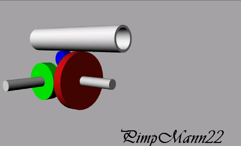
first off, thanks to pimpmann for this, he's a god =)
so, heres whatt you're seeing in these pictures
red-gear which rotates the pipe
green - gears coming off the red (main) gear, which hook into the wheel
Blue - Friction wheel which keeps the pipe moving foreward at a steady rate(original idea of using a tighteningf rope was scrapped and replaced with this
not pictured-
-small rollers (angled approx 45*) to keep the pipe moving straight, and on path
-crank/motor that gets the whole thing movin'
This is Pimp posting these pictures... The "real" poster will edit when he returns.
<img src="http://www.spudfiles.com/uploader/uploa ... evR-01.PNG">
<img src="http://www.spudfiles.com/uploader/uploa ... evR-02.PNG">
<img src="http://www.spudfiles.com/uploader/uploa ... evR-03.PNG">
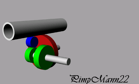