Machined pengun - Dimply
Hi guys,
Here's my very first pneumatic project, following a design JSR was kind enough to help me design and approve.
(guess who's fault it will be in case of failure?)
I'm happy to present you:
DIMPLY, the over engineered pengun
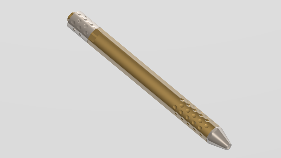
Well, that's the hypothetical and completely virtual 3D goal, of course... need some real work to do now
It will be able to fire 1/8" tiny ball bearings. Hopefully using pressure close to at least 400 psi (my shock pump limit).
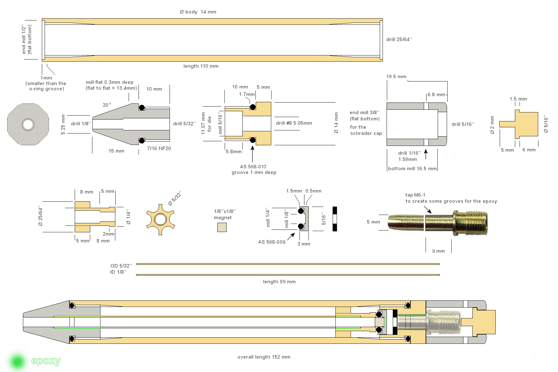
I have also prepared a plan with all the sizes, and I hope dewey1 or any 3D enthusiast will grab the pengun plan by its balls and make a cut drawing from that My 3D preview is really not more that a few rods and holes. Nothing is detailed internally. But I compensate the lack of detailed work using a shiny texture (in doubt, be shiny...)
Dimensional plan: 1 pixel = 1/10mm
Here's a great sectional view made by dewey1:
My intention is to post both picture results step by step, but also movies on YouTube showing the building process, so if you are curious about how someone that never learned of to machine properly can make a fool of himself right in front of a camera, please subscribe to this thread
I hope you'll enjoy what will follow.
Note: As a respectful homage to The Master, there's tiny amounts of epoxy used
For convenience to group all that I'll post following this thread, here are all the steps, video and cutting plans:
Step1: Video Plan
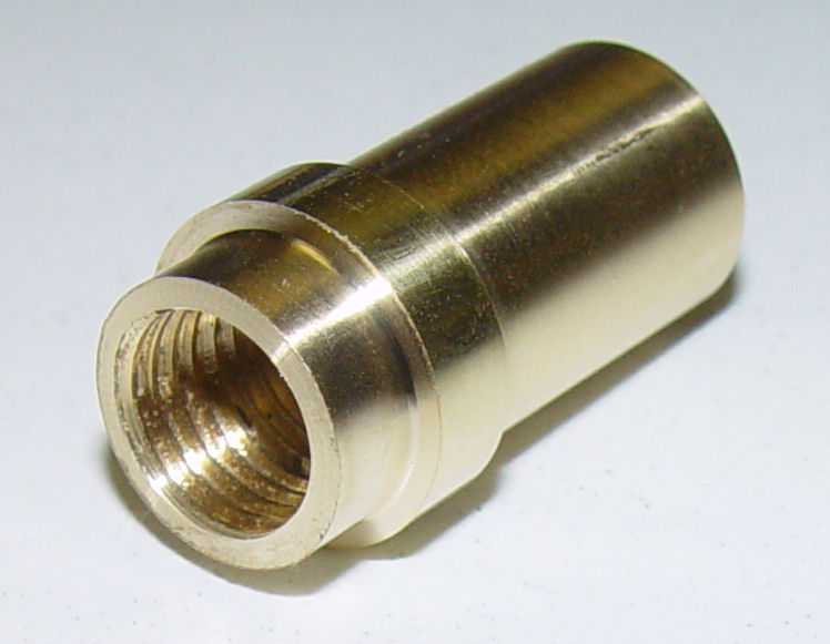
Step2: Video Plan
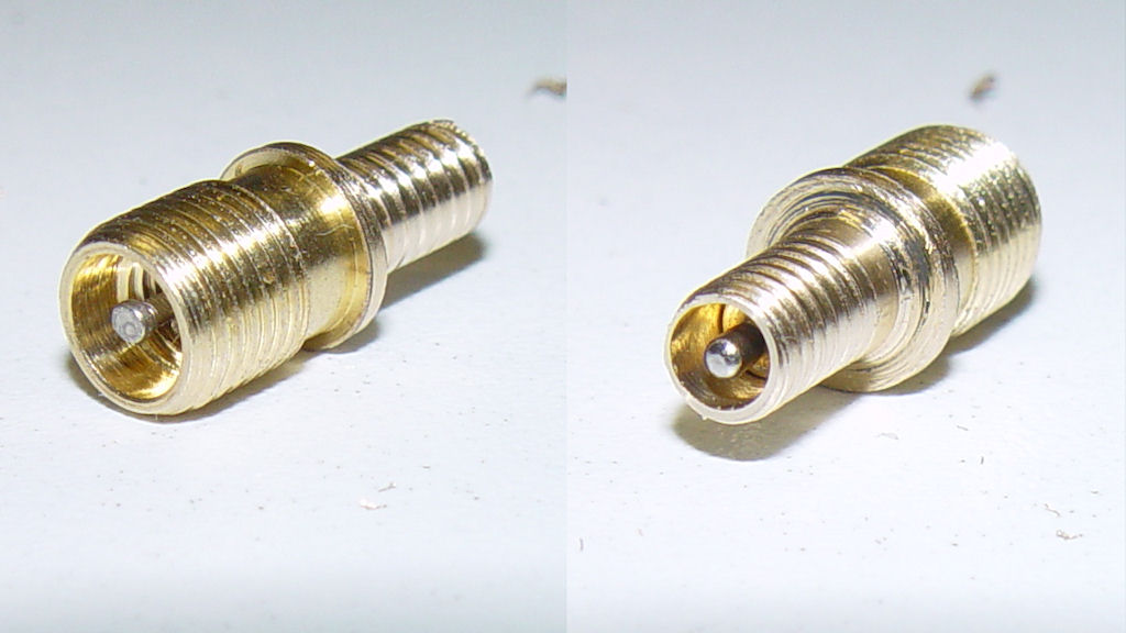
Step3: Video Plan
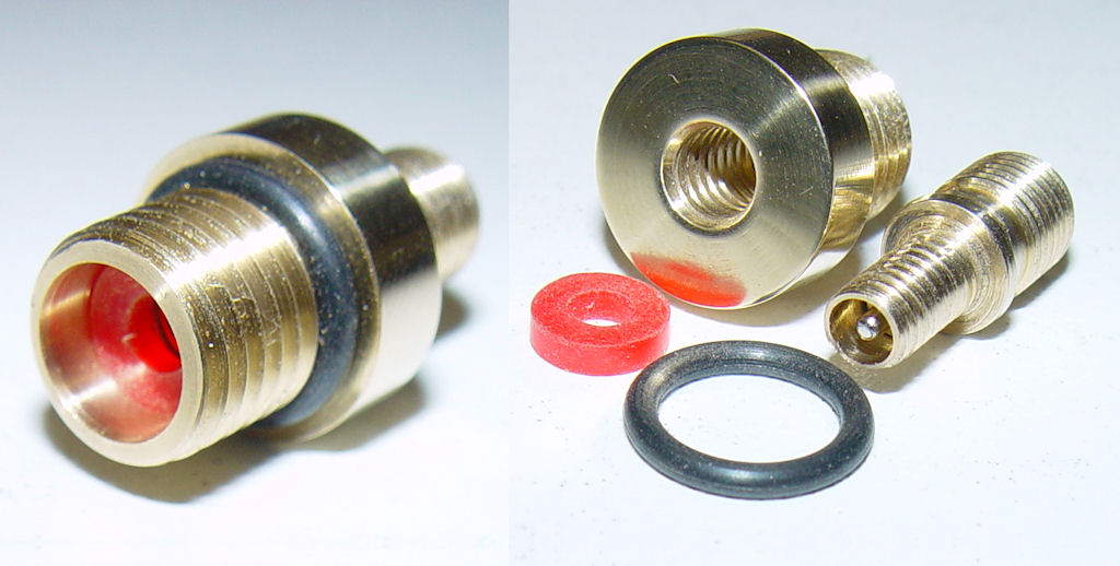
Step4: Video Plan
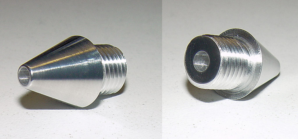
Step5: Video Plan
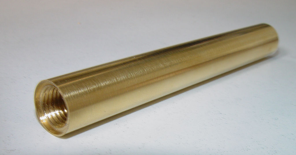
Step6: Video Plan
Step7: Video Plan
Step8: Video Plan
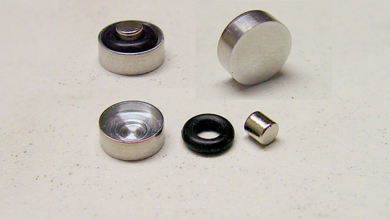
Step9A: Video Plan
Step9B: Video Plan
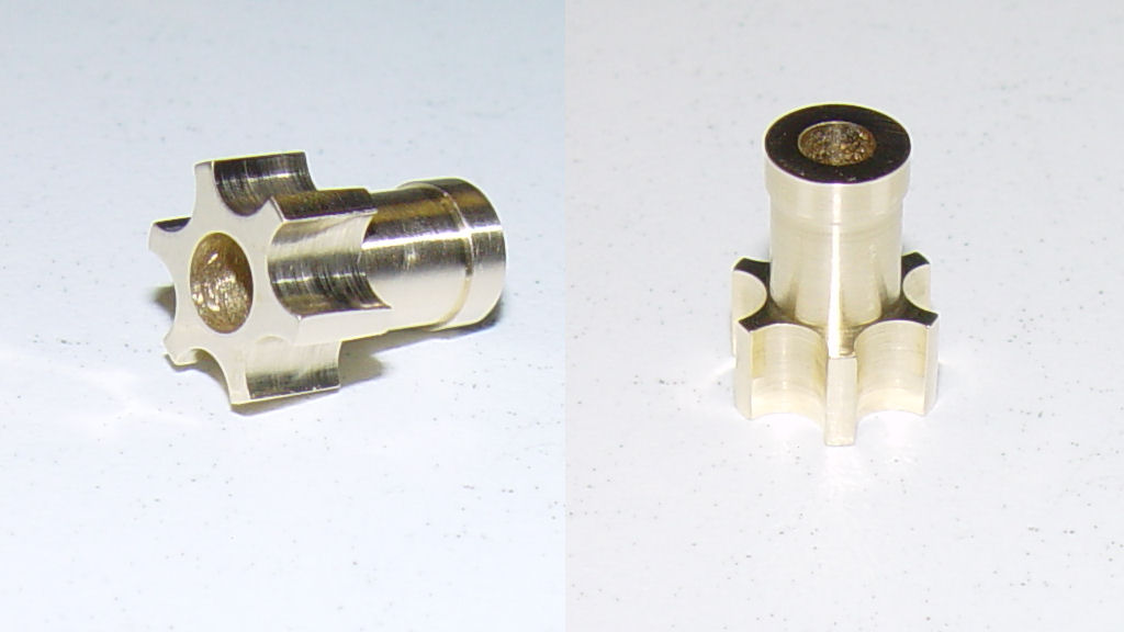
Step10: Video Plan
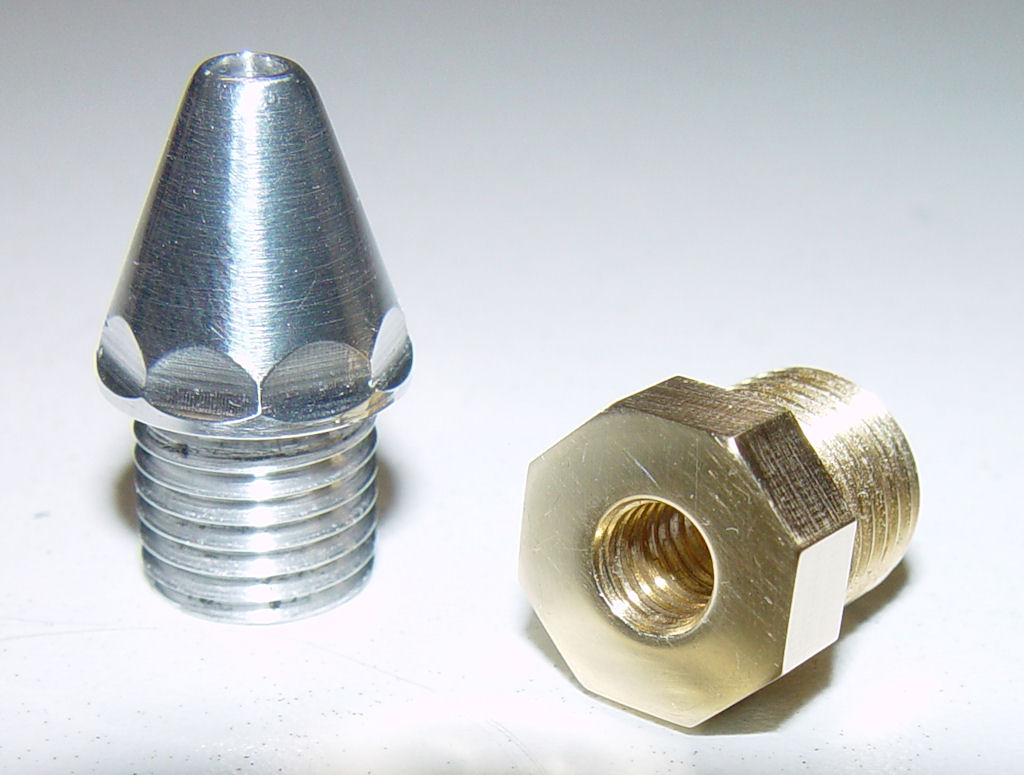
Step11A: Photo1 Photo2 Photo3 Plan
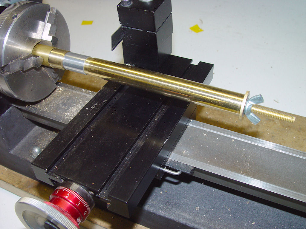
Step11B: Video Plan
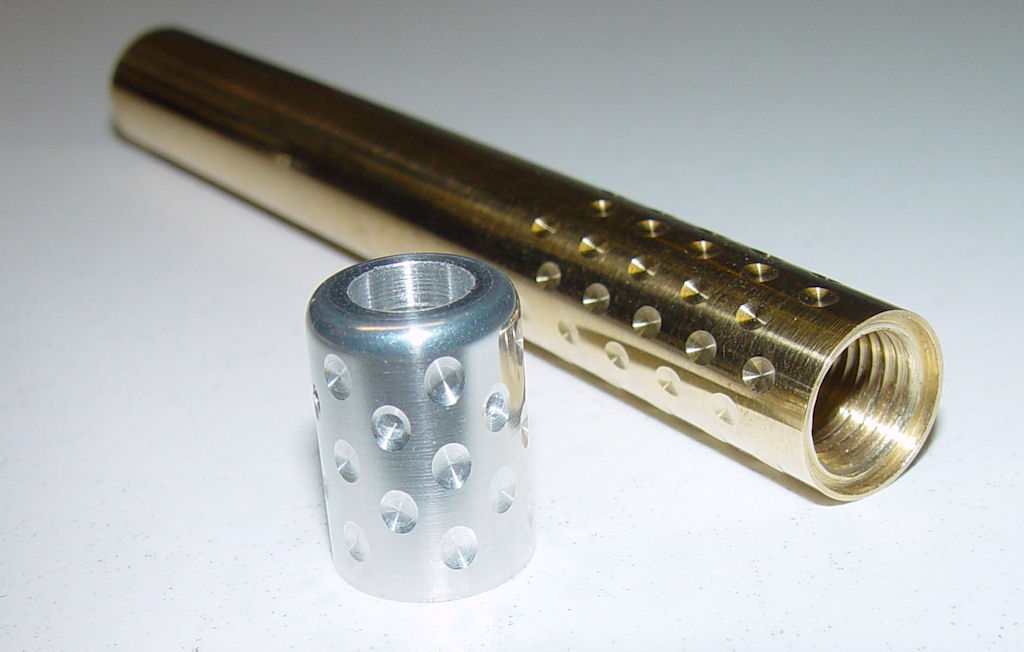
All the parts done
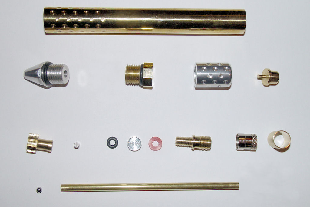
thanks to dewey-1 for the beautiful 3D work!
Step12: Video
Shooting tests Video
Here's my very first pneumatic project, following a design JSR was kind enough to help me design and approve.
(guess who's fault it will be in case of failure?)
I'm happy to present you:
DIMPLY, the over engineered pengun
Well, that's the hypothetical and completely virtual 3D goal, of course... need some real work to do now
It will be able to fire 1/8" tiny ball bearings. Hopefully using pressure close to at least 400 psi (my shock pump limit).
I have also prepared a plan with all the sizes, and I hope dewey1 or any 3D enthusiast will grab the pengun plan by its balls and make a cut drawing from that My 3D preview is really not more that a few rods and holes. Nothing is detailed internally. But I compensate the lack of detailed work using a shiny texture (in doubt, be shiny...)
Dimensional plan: 1 pixel = 1/10mm
Here's a great sectional view made by dewey1:
My intention is to post both picture results step by step, but also movies on YouTube showing the building process, so if you are curious about how someone that never learned of to machine properly can make a fool of himself right in front of a camera, please subscribe to this thread
I hope you'll enjoy what will follow.
Note: As a respectful homage to The Master, there's tiny amounts of epoxy used
For convenience to group all that I'll post following this thread, here are all the steps, video and cutting plans:
Step1: Video Plan
Step2: Video Plan
Step3: Video Plan
Step4: Video Plan
Step5: Video Plan
Step6: Video Plan
Step7: Video Plan
Step8: Video Plan
Step9A: Video Plan
Step9B: Video Plan
Step10: Video Plan
Step11A: Photo1 Photo2 Photo3 Plan
Step11B: Video Plan
All the parts done
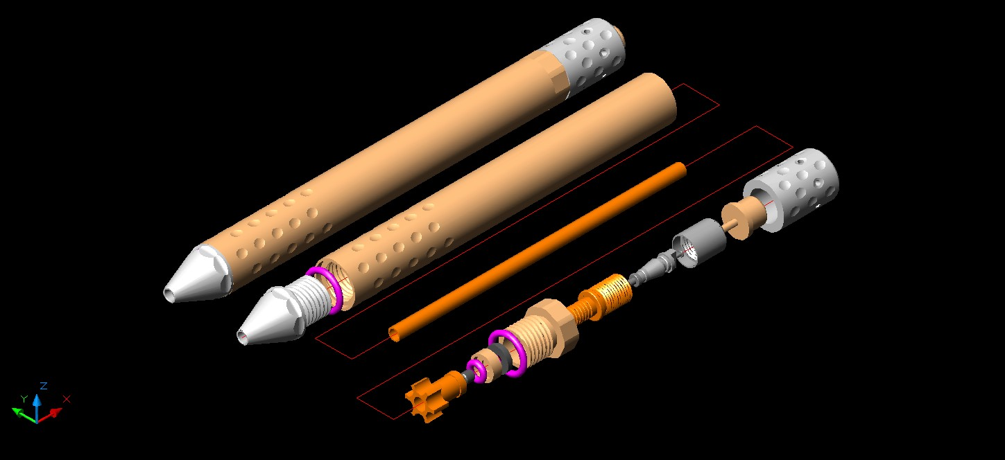
thanks to dewey-1 for the beautiful 3D work!
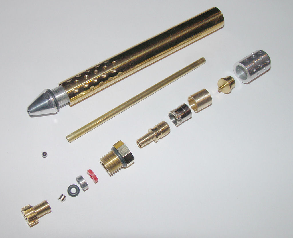
Step12: Video
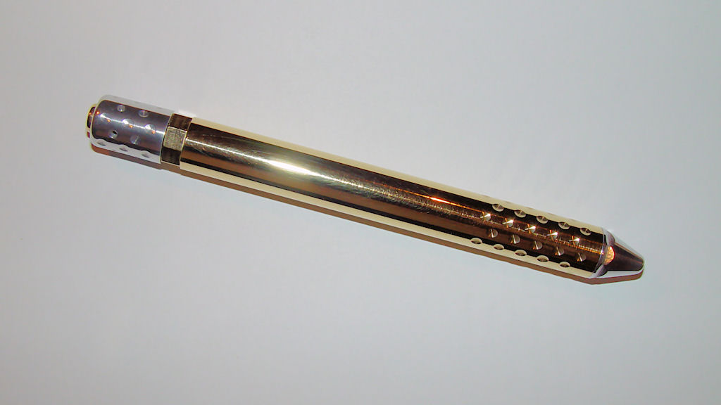
Shooting tests Video
Last edited by LeMaudit on Sat Jul 30, 2011 5:49 pm, edited 16 times in total.
I HAZ A BANG!
-
- Staff Sergeant 3
- Posts: 1769
- Joined: Mon Mar 21, 2011 5:41 pm
I'll try to fulfill your expectationsThis is going to be pretty cool when completed I think.
Exactly!Ball mill and rotary table?
I have cutting plans done, I will post them in parallel with the photos and videos so people interested can follow the building pretty much as if they were over my shoulder
And I'll be happy to read about criticism and suggestions for improvement of course. As I said, I'm pretty much self-taught, and my technique leave much room to improvement.
I HAZ A BANG!
- POLAND_SPUD
- Captain
- Posts: 5402
- Joined: Sat Oct 13, 2007 4:43 pm
- Been thanked: 1 time
JSR ji##### his pants in 3.... 2.... 1....
Children are the future
unless we stop them now
- exotechmaster
- Private
- Posts: 8
- Joined: Mon May 02, 2011 12:24 am
- Location: aust
looks mechanically sound on your blueprints
micro piston setup is so cool,
using the pilot as a pressure release trigger is nifty in something so small
what is your estimate on the range of this wee beasty
micro piston setup is so cool,
using the pilot as a pressure release trigger is nifty in something so small
what is your estimate on the range of this wee beasty
He'll be okay... he saw the design already...JSR ji##### his pants in 3.... 2.... 1....
I just hope it will be rigid enough I don't have a tailstock attachment for the mill... though this could be a VERY good reason to buy oneDo you plan on using a tailstock with the rotary table, or do you think it'll be ridged enough?
The dimples are only 0.3mm deep, that's not much, I think it will be okay.
Many members here made designs very similar if not identical to this one. Nothing really new. It's just for me a way to combine things I like: miniature, gun and pressure! The range I have no idea, it will not be that impressive in term of power I think... maybe going through a tin can? That's my best hope. You'll see some slo-mo for sure! (well, if the darn thing fire )using the pilot as a pressure release trigger is nifty in something so small
The goal for me is to start doing something pneumatic for real... my next project will be something of a different level completely... but that's too soon!
I HAZ A BANG!
Oooh I like the magnet !
A chamfer on the magnet might be a good idea, as I imagine it will be glued on. The piston has quite a short bearing surface when in forward position so, unless you have quite a tight tolerance, it might mean the magnet could touch the barrel seat.
As I'm sure you can achieve quite a good tolerance, maybe a simple scratch down the side of the piston or bore will be enough for filling.
How are you going to do the cuts on the barrel support, drill first then turn down ? Or just a 4mm cutting head ?
One thing you could try is making a rifling button, a rifled pen gun would be amazing Mmm or maybe save that for a bigger project !
Mmm in fact I should try and convince someone to machine me a rifling button, accuracy will always be limited if I making my tools with a dremel.
Damn! You found the secret place where the epoxy will be...al-xg wrote:A chamfer on the magnet might be a good idea, as I imagine it will be glued on.
neodymium magnet edges are a bit rounded. It should be okay. It will be pushed gently in place anyway, as the pressure increase below.
The tolerance should be very tight (I'll turn the diameter to custom fit whatever hole I drilled) and the magnet fit inside the barrel, so no problem if it is pushed a bit inside.The piston has quite a short bearing surface when in forward position so, unless you have quite a tight tolerance, it might mean the magnet could touch the barrel seat.
A 5/32" end mill cutting on the side. I'll describe that in details. For now I've almost finished filming the first step, I am learning how to make a niceeeee video out of it.How are you going to do the cuts on the barrel support, drill first then turn down ? Or just a 4mm cutting head ?
More this week-end.
I HAZ A BANG!
- inonickname
- First Sergeant 4
- Posts: 2606
- Joined: Sun Dec 07, 2008 3:27 am
Personally I'd simplify the piston...but at least its serviceable so you can fix it later if it fails
Looking good!
Looking good!
PimpAssasinG wrote:no im strong but you are a fat gay mother sucker that gets raped by black man for fun
commenting so i can get emails on the updates, but i may as well say it looks like a fantastic design and i would be completely happy to give the end result a home out of the kindness of my heart 8)
i think you have motivated me to get of my but and go fix my pen gun i make from a parker pen
why make it if it dosent shoot?
- jackssmirkingrevenge
- Five Star General
- Posts: 26203
- Joined: Thu Mar 15, 2007 11:28 pm
- Has thanked: 569 times
- Been thanked: 344 times
Finally, the curtain goes up but "Dimply"? lol.
I've seen the cutting plans and they are fantastically detailed, looking forward to seeing this take shape!
I don't think that will be necessary, without an o-ring it's not going to be a 100% seal anyway.
My one doubt is the o-ring seals for the threaded sections, but if in doubt, Araldite
With pen guns, "across the room" is the best you can hope forexotechmaster wrote:what is your estimate on the range of this wee beasty
Yep, we've been brainstorming for a couple of weeks, mostly yours truly saying what I want to do and LeMaudit pointing out what can and can't be done, as well as trying to add as many threaded sections as possible and eliminating use of epoxyHe'll be okay... he saw the design already...
I've seen the cutting plans and they are fantastically detailed, looking forward to seeing this take shape!
As I'm sure you can achieve quite a good tolerance, maybe a simple scratch down the side of the piston or bore will be enough for filling.
I don't think that will be necessary, without an o-ring it's not going to be a 100% seal anyway.
Rifling on a device that doesn't even have sights seems a bit redundant, but it would be interesting to achieve...One thing you could try is making a rifling button, a rifled pen gun would be amazing
We've been though several designs, this was my last one and I think it is the most elegant as it saves the need to cut a groove in the face of the piston to fit the o-ring while neatly incorporating the magnet to keep the prrojectile from rolling out.Personally I'd simplify the piston...but at least its serviceable so you can fix it later if it fails
My one doubt is the o-ring seals for the threaded sections, but if in doubt, Araldite
hectmarr wrote:You have to make many weapons, because this field is long and short life
iv hit my neighbors shed from at least 30m awayjackssmirkingrevenge wrote:With pen guns, "across the room" is the best you can hope forexotechmaster wrote:what is your estimate on the range of this wee beasty
why make it if it dosent shoot?
On the machined QEV I didn't get to finish, the max gap (on the diameter) between piston and the hole was intended to be 0.075mm, and the min gap 0.025mm with an N6 surface finish (Ra 0.8μm / 32μinch).I don't think that will be necessary, without an o-ring it's not going to be a 100% seal anyway.
I did not want to post this after realising how creepy it was (that steel bung, is just a fixture for machining, it is not part of the QEV design)
With any sort of lube on that, filling would be painfully slow or not even work.
I'm pretty sure oblong projectiles would tumble within the effective range of the pengun, it's not really about accuracy just keeping projectile tip forward.Rifling on a device that doesn't even have sights seems a bit redundant, but it would be interesting to achieve...
It would be pretty useless on the ball bearings though.